Stand-In: Visibility culling
This how-to will walk you through how to apply visibility culling on a Stand-In of which purpose is to be seen from limited view-angles (a.k.a view-dependent LOD). See concepts for more specific details about visibility culling.
To create a view-dependent Stand-In, please follow the steps below:
1. Select Static Mesh Actor(s).
Select the Static Mesh Actor(s) you wish to perform visibility culling on.
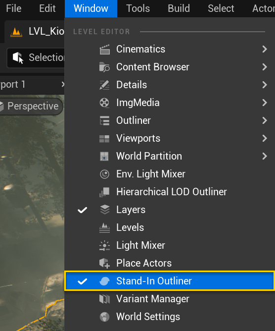
2. Open the Stand-In Outliner.
Open the Stand-In outliner, it is located under Windows → Stand-In Outliner.
3. Create a Stand-In Mesh Actor.
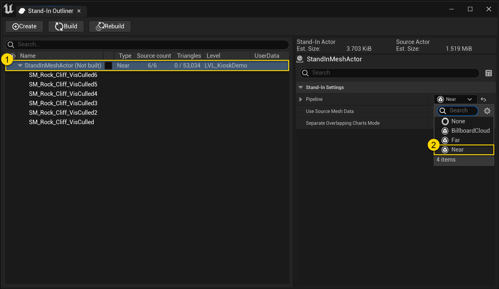
To create a Stand-In Mesh Actor, click Create in the Stand-In outliner toolbar (1). The Stand-in Mesh Actor (and its source Actors) should now be visible in the outliner below (2).
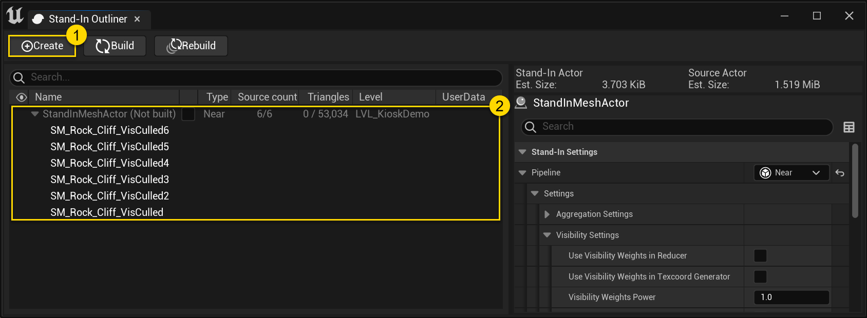
4. Choose optimization method.
Select the newly created Stand-In Mesh Actor in the list below. In the right-most settings panel; under Stand-In Settings, specify which Pipeline to use for optimization. Both Near- and Far Stand-Ins support visibility culling. In this example we'll use Near as the resulting Actor will be seen from up-close.
5. Set visibility settings.
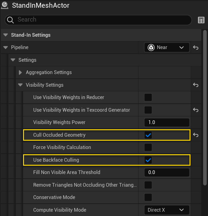
Navigate to Pipeline → Settings → Visibility Settings and enable Cull Occluded Geometry, also verify that Use Backface Culling is enabled. It is also recommended to enable Use Visibility Weights in Texcoord Generator when material baking is active, as it will result in better texture utilization.
6. Setup a Nav Mesh Volume.
Simplygon's visibility culling is dependent on Unreal Engine's Nav Mesh Volumes. There are two important parts of a Nav Mesh; Nav Mesh Bounds Volume and Nav Mesh Modifier Volume. The Bounds Volume sets the extremes while the Modifier Volume excludes itself from the Nav Mesh Volume.
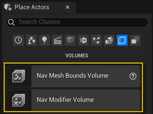
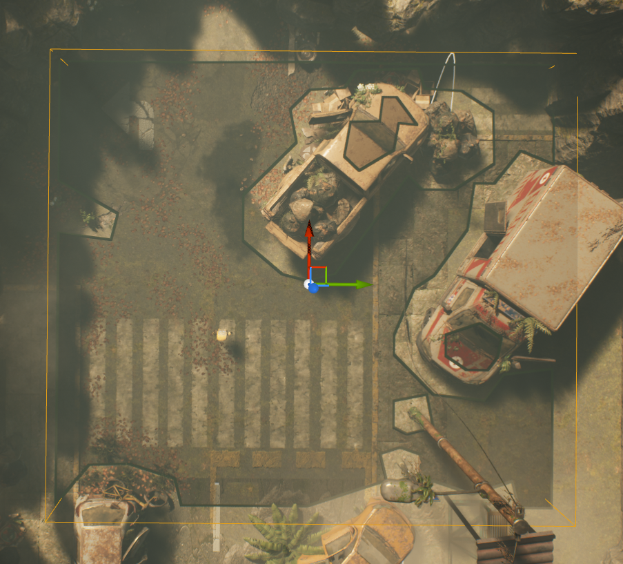
To setup a Nav Mesh for the current level, navigate to Windows → Place Actors. Drag in a Nav Mesh Bounds Volume and set the dimensions so that the volume covers the walkable space of where the view-dependent LOD should be visible from.
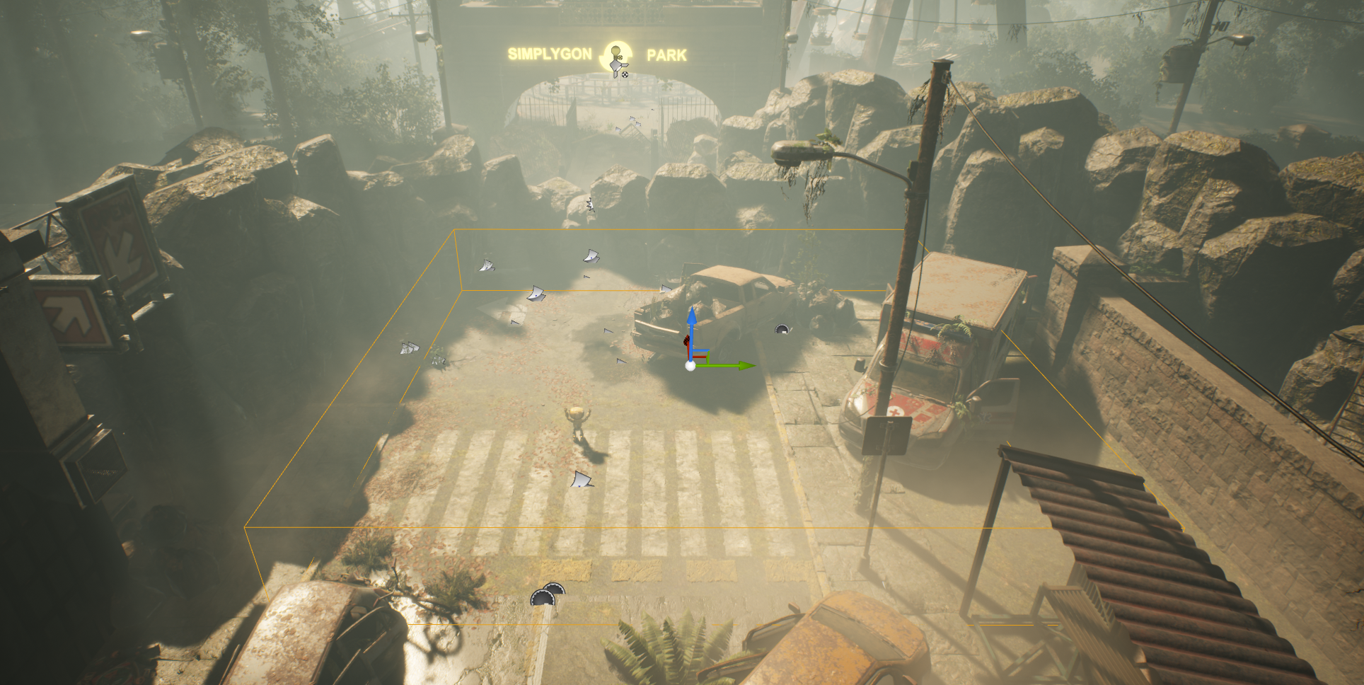
To view the current navigable area in the Nav Mesh Volume, go to Show → Navigation. Also, make sure that the navigation is up-to-date through Build → Build Paths.
7. [Optional] Exclude areas from Nav Mesh Volume
Place one or more Nav Mesh Modifier Volumes in the level to exclude these parts from the Nav Mesh Bounds Volume.
8. Setup a Simplygon Visibility Sampler Visualizer.
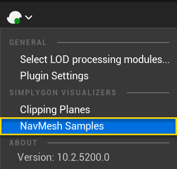
Go to Simplygon → Nav Mesh Samples to create a SimplygonVisibilitySamplerVisualizer for the current level.
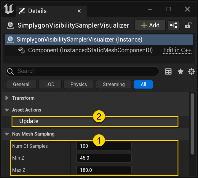
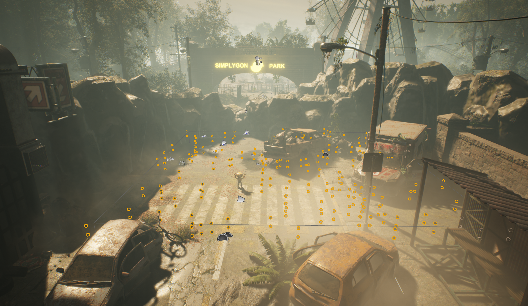
The SimplygonVisibilitySamplerVisualizer contain settings that can be tweaked, such as Number of Samples (1) which potentially can increase the quality of the culling, at the cost of computations. Click Update (2) to generate / regenerate the sample points inside the level's Nav Mesh Bounds Volume.
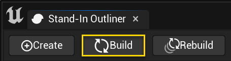
9. Build Stand-In.
Finally, click Build (or Rebuild if the Stand-In has been built before) in the Stand-In outliner and wait for the optimization to complete.
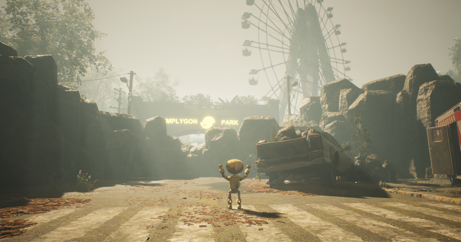
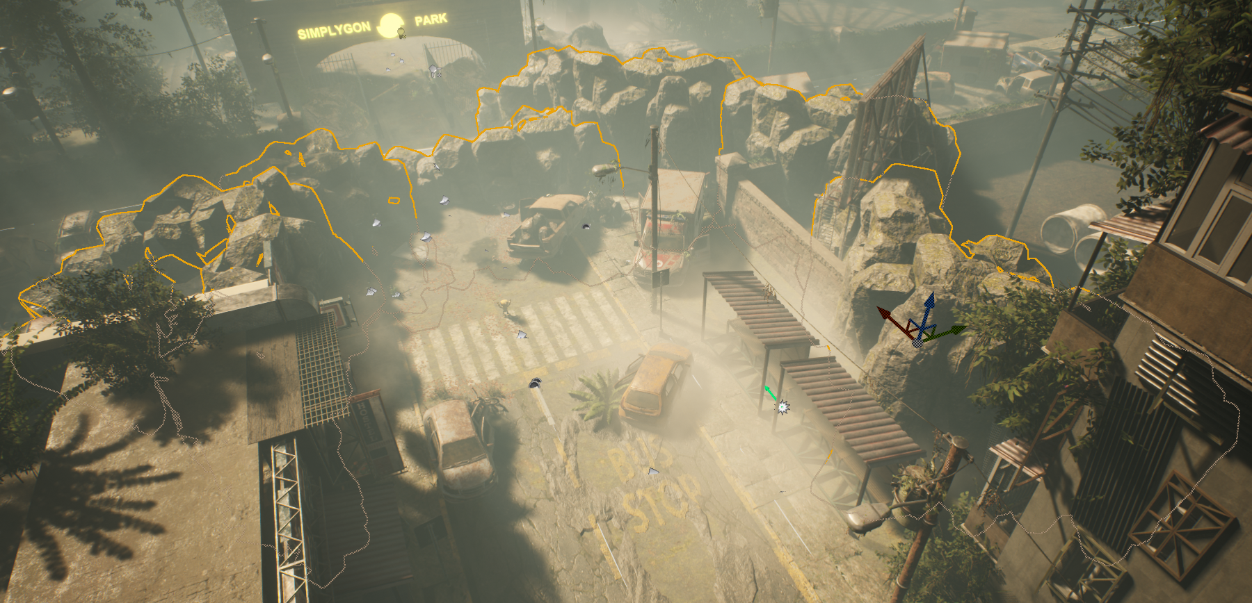
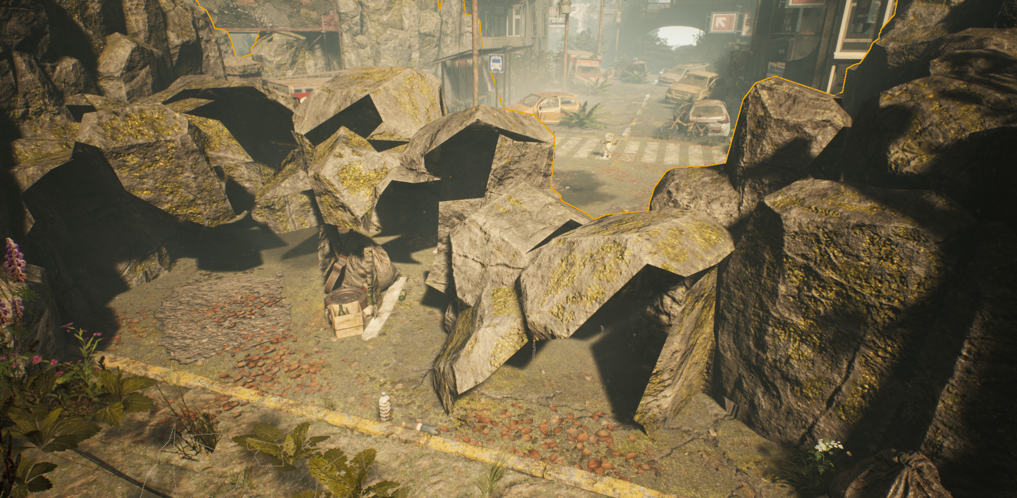
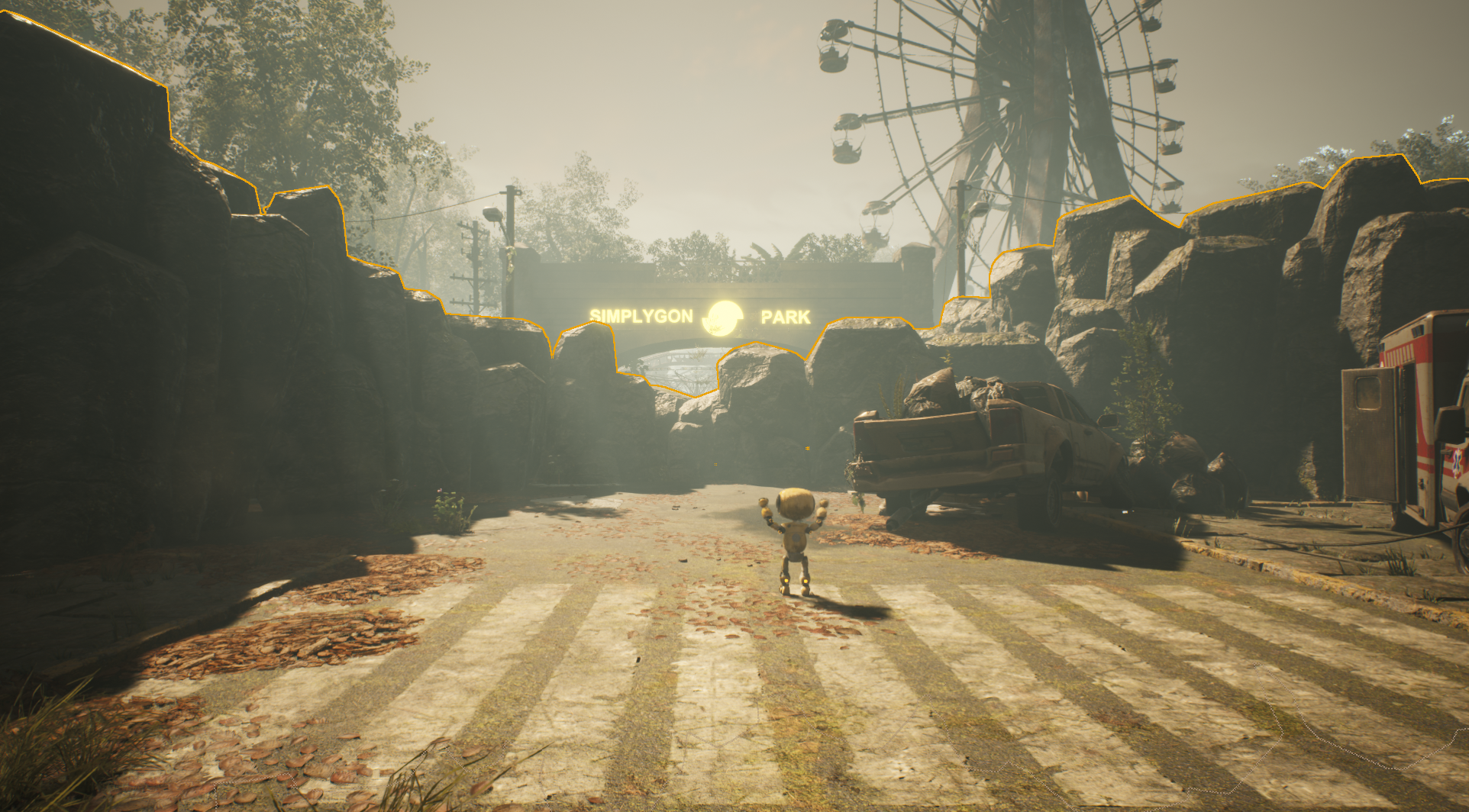
10. Result.
The resulting Stand-In is now view-dependent; all triangles that are not visible from inside the visibility volume (Nav Mesh Volume) have been removed. Some triangles that are facing Poly's negative view direction can be seen from the extremes of the visibility volume, and will therefore be kept.
Visibility culling can also be used in combination with Clipping Planes / Clipping Geometries to strip away parts of Static Mesh Actors that are piercing through the ground.