Remeshing - 
The Remeshing component creates a new geometry that is based on the input geometry but topologically based on the size of the input geometry, rendered at a specific screen size (where a larger number means it should be cover more pixels on the screen, i.e. a more detailed mesh is obtained).
Tip
Check out the Remeshing article to learn more about the Remeshing processor.
Main settings
Pixels (on-screen size)
The targeted on-screen rendering size of the geometry. The error of the silhouette will be at most 1 pixel when viewed at the specified on-screen size.Surface transfer mode
Determines whether processing shall prioritize speed (Fast) or quality (Accurate).Merge distance (pixels)
Holes, cavities and empty spaces in the mesh smaller than the specified value (in pixels) will be removed. Large values may cause merging of distant objects. The specified value is capped to the on-screen size of the remeshing.Max triangle size
The maximum size in pixels of a generated triangle.Selection set
If set, only the specific geometries in the selected selection set will be processed, otherwise the whole scene will be processed.Transfer colors
If enabled, transfers the vertex colors from the original mesh to the generated LOD.
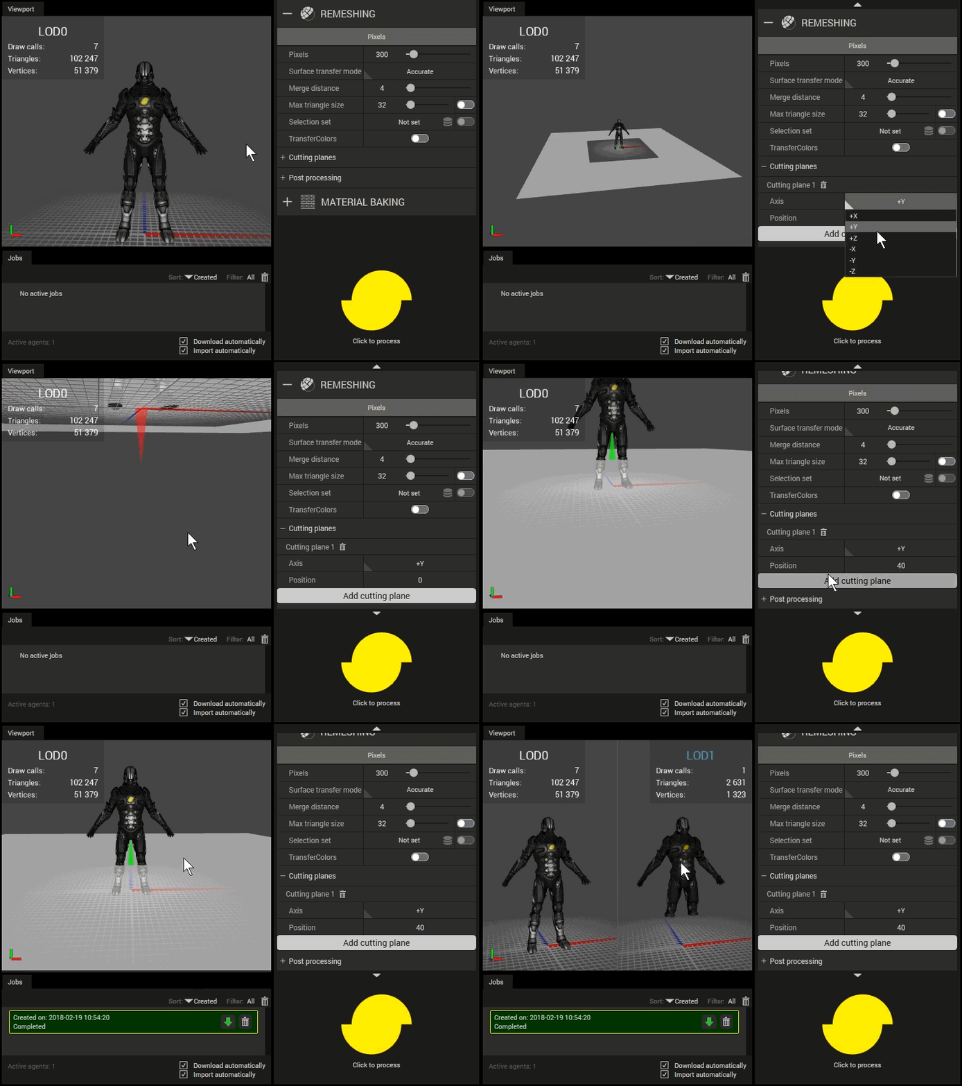
Cutting planes
Click the Add cutting plane button to add a cutting plane. The cutting plane will be visualized in the Viewport (once a scene has been loaded) according to the selected axis and position value.
The green/red arrows indicate which side that will be kept/removed.
Axis
The defining axis of the axis aligned cutting plane.Position
The offset of the axis aligned cutting plane.
To remove a cutting plane, click the trashcan button 

Using cutting planes.
Post processing
Final task of the remeshing processor.
- Hard angle cutoff
The edge angle in degrees above which an edge is considered "hard". If the angle between two triangles is above the specified value, the normals will not be smoothed over the edge between those two triangles.