Visibility / culling using geometry as camera mesh
This tutorial expands the concept of using visibility information to guide the Simplygon processor. Here we are going to show how you setup and use the vertices of an arbitrary geometry to setup visibility camera to aid Simplygon processors.
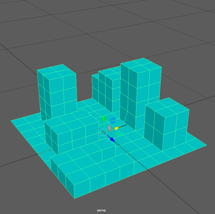
The first step is to create an asset, in this example we'll use a plane surface and extrude faces on it to make it resemble a miniature city. This asset is what we are going to process and reduce.
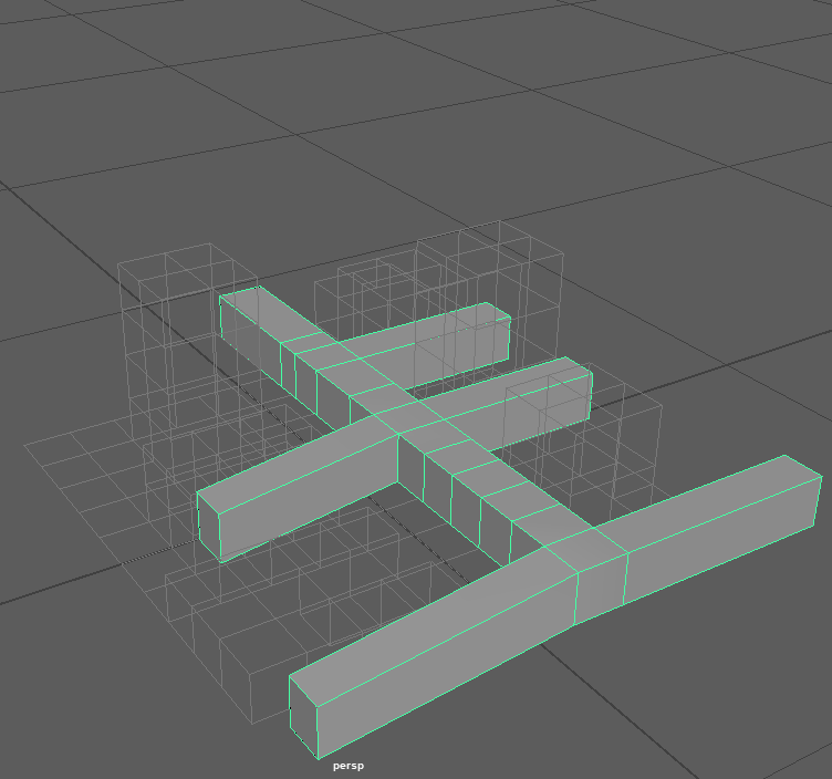
The next step is we take a cube and extrude faces and subdivide it to follow the open areas in the miniature city to allow for coverage. It almost resemble a bone structure. This geometry will be used as a camera mesh. The vertices of the mesh would be converted to omnidirectional cameras looking along positive and negative direction along X,Y and Z.
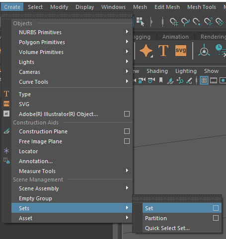
The next step is to create a selection-set with the camera mesh selected. And lets call it the "cameraMeshes".
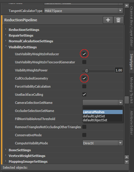
Next we create the pipeline. Click on Add LOD Component -> Advanced -> Reduction to create a Reduction Pipeline. The reduction ratio is by default set to 0.5 (50%) so let's go with that in this tutorial. Now expand VisibilitySettings and check UseBackfaceCulling , UseVisibilityWeightsInReduces and CullOccludedGeometry, and in the CameraSelectionSetName dropdown, choose the selection-set named "cameraMeshes".
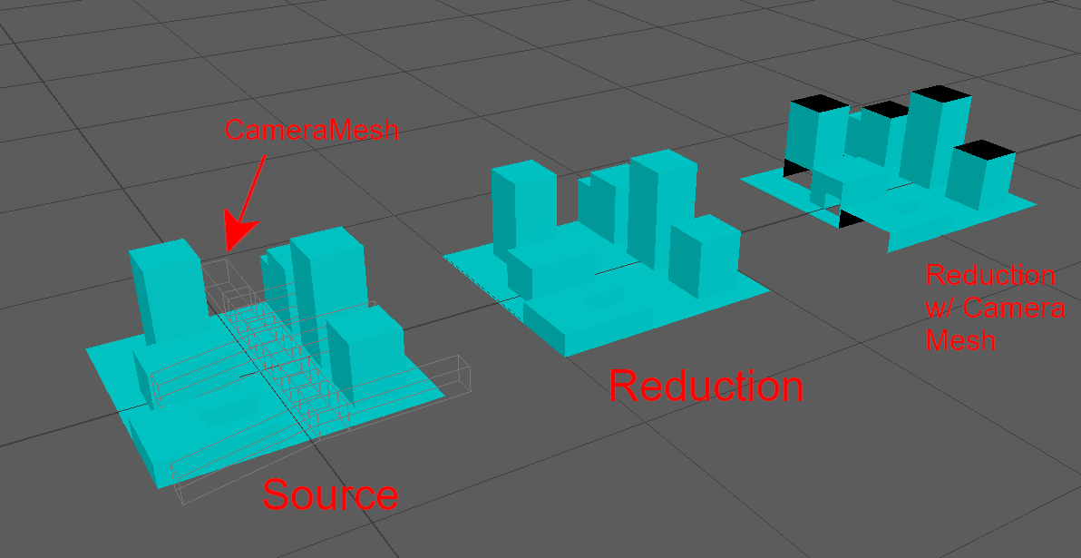
The final step, select the asset in the Viewport or Outliner, then press the yellow Simplygon icon in the Simplygon UI to start the optimization. When the optimization has completed the result will be returned to Maya. The following image illustrates the source inputs( geomety to process plus camera mesh geometry). The resulting mesh from a standard reduction process and result from reduction using the "cameraMeshes" to setup visibility camera paths.