Simplygon exposes several different distinct processing paths:
Reduction processing where geometries are reduced in triangle count using re-linking of triangles and vertex removal.
Remeshing processing where the geometries are replaced by a lightweight proxy geometry that resembles the original.
Aggregation processing where the geometries are combined into a single geometry with one shared UV atlas.
Impostor processing where the geometries are replaced by a single two-triangle plane, set to resemble the original from a specific viewing angle.
Occlusion processing replaced by a lightweight proxy geometry that mimics the silhouette of the input geometry.
These paths are exposed through processing objects, which are derived from the IProcessingObject interface, which defines generic methods for running a processing, and receiving information on the progress of the processing. The processing objects are called IReductionProcessor, IRemeshingProcessor, IAggregationProcessor, IImpostorProcessor and IOcclusionMeshProcessor respectively.
Event handling
The processing objects supports the progress event, SG_EVENT_PROGRESS. For details regarding event handling, see the section on event handling.
Example
// Progress observer class that prints progress to stdout.
class progress_observer : public robserver
{
public:
virtual void Execute(
IObject *subject ,
rid EventId ,
void *EventParameterBlock ,
unsigned int EventParameterBlockSize )
{
// Only care for progress events.
if( EventId == SG_EVENT_PROGRESS )
{
// Get the progress in percent.
int val = *((int*)EventParameterBlock);
// Tell the process to continue.
// This is required by the progress event.
*((int*)EventParameterBlock) = 1;
// Output the progress update.
printf( "Progress: %d%%\n" , val );
}
}
} progress_observer_object;
void RegisterEventObserver( spReductionProcessor red )
{
// Register the event observer class with the reducer.
// Tell it we want progress events only.
red->AddObserver( &progress_observer_object , SG_EVENT_PROGRESS );
}
Settings objects
As the processing objects have a lot of settings, and some settings are also shared between them, most of the settings are grouped into setting objects}. The setting objects contain settings that are naturally grouped together, such as pre-processing settings, main-processing settings and post-processing settings. Setting objects that are used by multiple processors will be listed below, and setting objects that are used only by once processor is listed under that processor in the following sections.
Mapping image settings
Applies to processors: ReductionProcessor, RemeshingProcessor, ImpostorProcessor, AggregationProcessor.
Simplygon can generate one or more mapping images, which can be used to cast material data from the original geometry onto the reduced geometry after the processing has completed. A Mapping image is basically a texture on the reduced geometry where each pixel contains information of which triangle and barycentric coordinate on the original geometry that the pixel corresponds to.
The settings contains basic things like the desired texture dimensions of the mapping image to create. There are also setting for if new texcoords should be generated, and then how the texcoords should be generated on the processed mesh. They can either be created from scratch when using the Parameterizer, purely based on LOD geometry, or be created from the original texcoords when using the ChartAggregator. Some settings has a prefix which means they are only relevant when the corresponding GeneratorType is used.
Multiple mapping image generation currently only works with the ReductionProcessor. For more on how to use multiple mapping images, check the multi material casting example.
Example
The following example shows how to generate a mapping image.
void SetMappingImageSettings( spReductionProcessor reducer )
{
// Fetch the mapping image settings object from the reducer
spMappingImageSettings settings = reducer->GetMappingImageSettings();
// Set the mapping image settings for this processing
settings->SetGenerateMappingImage(true);
settings->SetUseAutomaticTextureSize(false);
settings->SetParameterizerUseVertexWeights(false);
settings->SetWidth(1024);
settings->SetHeight(1024);
settings->SetGutterSpace(5);
}
Bone reduction settings
Applies to processors: ReductionProcessor, RemeshingProcessor.
Simplygon is able to reduce the number of bones used in animation by re-linking vertices to different bones. The user can both select a maximum number of bones allowed per vertex and limit the total number of bones used in the scene. Simplygon can either automatically detect which bones are best suited to be removed, or the user can manually select which bones to keep or removed using selection sets.
Example
The following example shows how to use the bone reduction settings. For more, see the bone reduction example.
void SetBoneReductionSettings( spReductionProcessor reducer )
{
// Fetch the bone settings object from the reducer
spBoneSettings settings = reducer->GetBoneSettings();
// use ratio processing and set LOD ratio to 0.5
settings->SetBoneLodProcess(SG_BONEPROCESSING_RATIO_PROCESSING);
settings->SetBoneLodRatio(0.5);
}
Visibility settings
Applies to processors: ReductionProcessor, RemeshingProcessor.
Visibility can be computed for the scene or for a selected subset by using selection sets. This is done to determine which parts of the scene is actually visible. Scene cameras are added to the scene and the user can select which cameras should be used when calculating the visibility. If no cameras are selected, then a default set of cameras surrounding the scene will be used. The generated visibility weights can be used to guide the reduction, texcoord creation or used to simply remove all triangles that never are visible.
Example
The example below shows how to enable the visibility weights for the reducer and places a static camera in front of the object. For a more detailed example see Visibility Weight example.
void SetVisibilitySettings( spReductionProcessor reducer )
{
// Fetch the visibility settings object from the reducer
spVisibilitySettings vs = reducer->GetVisibilitySettings();
// Enable for both reduciton and texcoord generation
vs->SetUseVisibilityWeightsInReducer( true );
vs->SetUseVisibilityWeightsInTexcoordGenerator( true );
//Create a camera
spSceneCamera sceneCamera = sg->CreateSceneCamera();
//Get the camera position and target position
spRealArray cameraPositions = sceneCamera->GetCameraPositions();
spRealArray targetPositions = sceneCamera->GetTargetPositions();
//Set the tuple count to 1
cameraPositions->SetTupleCount(1);
targetPositions->SetTupleCount(1);
// Have the camera in (0, 0, -3)
// Have it point to origin ( center of model )
real xyz[] = {0.0f,0.0f,-3.0f};
real target[] = {0.0f,0.0f,0.0f};
cameraPositions->SetTuple(0, xyz);
targetPositions->SetTuple(0, target);
// Sets the camera coordinates to use normalized coordinates
sceneCamera->SetUseNormalizedCoordinates( true );
if(sceneCamera->ValidateCamera()) //If the camera is setup correctly
{
scene->GetRootNode()->AddChild(sceneCamera);
spSelectionSet set = sg->CreateSelectionSet();
set->AddItem(sceneCamera->GetNodeGUID());
rid setID = scene->GetSelectionSetTable()->AddItem(set);
visibilitySettings->SetCameraSelectionSetID(setID);
}
}
Repair settings
Applies to processors: ReductionProcessor.
Welding consists of merging vertices that are closer than a certain distance from each other. This is often used as a pre-processing step to make sure that the geometry is properly connected. Geometry information imported from file formats that do not use vertex indexing have to be welded or gaps between the triangles would be introduced when simplifying it.
T-junction removal is also performed by the reducer processor as a pre-processing step. A T-junction is when a vertex is very close to an edge causing a small gap between the triangles. This is solved by splitting the edge at the projection of the vertex onto the edge and then then merging the two vertices.

T-Junction processing before and after
Example
void SetRepairSettings( spReductionProcessor reducer )
{
// Fetch the repair settings object from the reducer
spRepairSettings repair_settings = reducer->GetRepairSettings();
// Set the weld and T-junction distances
repair_settings->SetWeldDist(real(0.25));
repair_settings->SetTjuncDist(real(2));
}
Normal calculation settings
Applies to processors: ReductionProcessor.
After reduction has completed, the reducer can optionally generate new normals on the reduced geometry. These settings control how these new normals are calculated.
Example
The following example shows how to use the normal calculation settings in the reducer
void SetNormalCalculationSettings( spReductionProcessor reducer )
{
// Fetch the normal calculation settings object from the reducer
spNormalCalculationSettings settings = reducer->GetNormalCalculationSettings();
// tell the reducer to generate new normals
settings->SetGenerateNormals(true);
settings->SetScaleByArea(true);
settings->SetScaleByAngle(true);
settings->SetHardEdgeAngle(75.0f);
}
Reduction vs Remeshing
The Simplygon API provides two main ways of performing optimization. These include the reduction processor and the remeshing processor. The difference between the two approaches is that reduction processor uses data from the original geometry, as well as preserves this data like UV sets, materials, textures and normals. The remeshing processor instead creates a completely new set of data including combining various geometries into one, creating a new UV set and merging materials and textures. The following table illustrates some common cases where to use which approach.
Reduction Processor |
Remeshing Processor |
Preserving original texture data |
Combining multiple object |
Background objects nearby |
Background distant objects |
Overall triangle reduction |
For mobile 3D content |
|
For reducing draw calls |
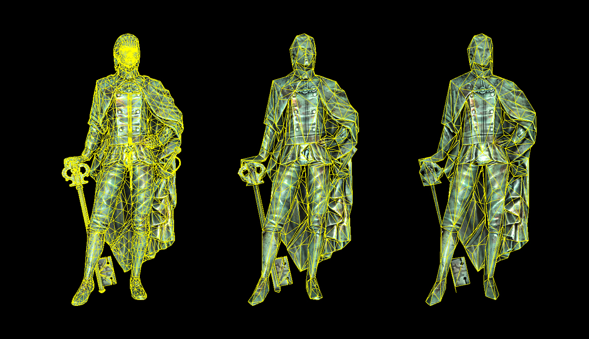
Silhouette preservation using the reduction processor
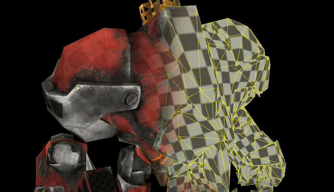
UV preservation using the reduction processor
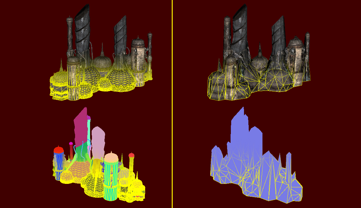
Topological reduction using the remeshing processor
Reduction processor
By modifying the existing data in a GeometryData object, a lighter version of the geometry is created. First it cleans up the geometry through welding, T-junction removal and double triangle removal. Then it re-links and removes triangles to decimate the triangle/vertex count, doing a very good job at preserving vertex/triangle-data, such as texture coordinates and geometry group IDs. It can re-calculate the normals of the modified geometry, and calculate texture coordinates for the geometry. Finally it can create new diffuse, ambient, specular, displacement and normal maps based on the original geometry. Normal maps can be both world space and tangent space, and can be based either on the normals of the original geometry, or a normal map used by the original geometry.
For more on how to use the reduction processor, see the reduction example.
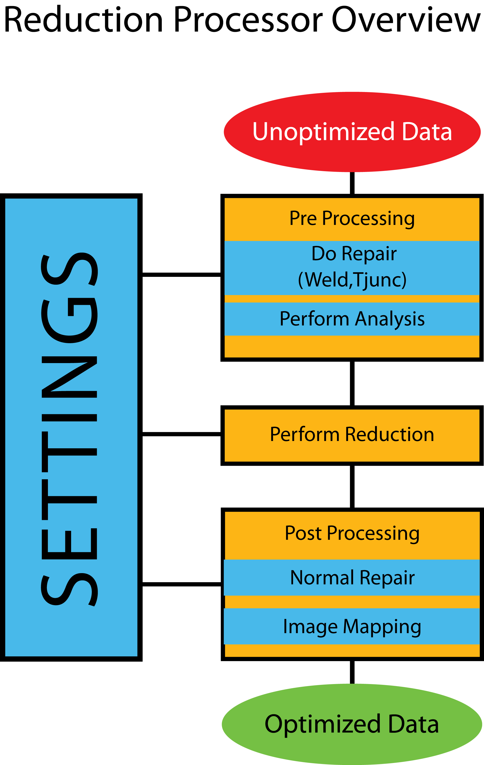
Simplygon Reduction Processor Overview
Reduction settings
Handles all the settings for Simplygon's simplification algorithms. The user can tell the reduction processor the relative importance of features using the Set{feature}Importance methods (or disabling an importance entirely by setting it to 0.0). The user may also specify to what extent the reducer is allowed to modify the vertex data from the original model when creating LODs, as well as other useful settings.
void RunReductionProcessor(spScene scene)
{
spReductionProcessor reducer = sg->CreateReductionProcessor();
reducer->SetScene( scene );
// Fetch the reduction settings object from the reducer
spReductionSettings settings = reducer->GetReductionSettings();
// Set shading to half as important as default
settings->SetShadingImportance( 0.5 );
// Set material boundary to be twice as important as default
settings->SetMaterialImportance( 2.0 );
// Set UVs to not be taken into account at all
settings->SetTextureImportance( 0.0 );
// Set data creation preferences to allow the reducer
// to modify all vertex data
uint restriction = SG_DATACREATIONPREFERENCES_PREFER_OPTIMIZED_RESULT;
settings->SetDataCreationPreferences( restriction );
//The reduction stops when any of the targets below is reached
settings->SetStopCondition(SG_STOPCONDITION_ANY);
//Selects which targets should be considered when reducing
settings->SetReductionTargets(SG_REDUCTIONTARGET_ALL);
//Targets at 50% of the original triangle count
settings->SetTriangleRatio(0.5);
//Targets when only 10 triangle remains
settings->SetTriangleCount(10);
//Targets when an error of the specified size has been reached.
//As set here it never happens.
settings->SetMaxDeviation(REAL_MAX);
//Targets when the LOD is optimized for the selected on screen pixel size
settings->SetOnScreenSize(50);
reducer->RunProcessing();
}
void SetEdgeSelectionSetImportance(spReductionProcessor red,
spGeometryData geom)
{
geom->AddBaseTypeUserCornerField(
SimplygonSDK::BaseTypes::TYPES_ID_BOOL,
"EdgeSelectionSet",
1
);
spBoolArray EdgeSelectionSetEdges(
IBoolArray::SafeCast(geom->GetUserCornerField("EdgeSelectionSet"))
);
//Set the edges you want to be respected
EdgeSelectionSetEdges->SetItem(edgeID, true);
// Set the Reduction Settings.
spReductionSettings reduction_settings = red->GetReductionSettings();
//Set the custom importance setting for the border edges
reduction_settings->SetEdgeSetImportance( 2.0f );
}
Remeshing Processor
Remeshing differs from reduction in that the geometries are replaced by a lightweight proxy geometry that resembles the original, but does not share vertex data or parts of the original mesh data. Instead, the remeshing processor is allowed to generate a mesh based on the maximum size of the proxy object on-screen, and can freely fill holes and place triangles that overlap gaps in the original mesh. Also, as the proxy mesh is assumed to be viewed from the outside, any interior mesh that cannot be seen, is removed. The result is a very light-weight mesh that is highly optimized for real-time viewing, or to speed up off-line rendering of small objects.
The remesher has fewer settings than the reducer, and in most cases the generated mapping image is used to reproduce details on the geometry using baked textures. Most of the time, only the onScreenSize setting needs to be adjusted, apart from the mapping image settings to choose texture quality. For more on how to use remeshing, see the remeshing example.
Remeshing settings
Simplygon is capable of remeshing arbitrary geometry, including non-manifold surfaces. The resulting geometry is guaranteed to be a closed 2-manifold. The settings contained in the remeshing settings control the parameters of the new mesh that is to be generated.
Example
The following example shows how to set remeshing parameters.
void RunRemeshingProcessor(spScene scene, unsigned int screenSize,
unsigned int mergeDistance)
{
spRemeshingProcessor remesher = sg->CreateRemeshingProcessor();
// Fetch the remeshing settings object from the remesher.
spRemeshingSettings settings;
settings = remesher->GetRemeshingSettings();
settings->SetOnScreenSize(screenSize);
settings->SetMergeDistance(mergeDistance);
remesher->SetScene(scene);
remesher->RunProcessing();
}
Mapping image settings
This is the same settings as in the reducer, please see the appropriate section for more information.
Impostor processor
In contrast to the reduction and remeshing processors, the impostor processor will always generate a two-triangle plane to replace the original geometry. This plane is scaled, positioned and oriented in such a way as to perfectly represent the original geometry from a specific viewing angle, assuming that materials are cast after the processor has generated the impostor geometry and the mapping image. Also in contrast to the reduction and remeshing processors, the impostor processor does not replace the input geometry or scene with the generated impostor geometry to simplify making multiple impostors from different angles.
For a well-commented example of basic usage of the impostor processor, see the impostor example.
Impostor settings
This settings object contains the settings for the impostor generation that is performed by the impostor processor. These settings include parameters like what direction the impostor should be generated from, z-position, and the extents of the generated billboard.
Example
The following example shows how to use the ImpostorProcessor
void RunImpostorProcessing(spScene scene)
{
spImpostorProcessor impProc = sg->CreateImpostorProcessor();
// Fetch the impostor settings object and set settings
spImpostorSettings settings;
spMappingImageSettings msettings;
settings = impProc->GetImpostorSettings();
real view[3] = {1.0f, 0.0f, 0.0f};
settings->SetUseTightFitting(true);
settings->SetViewDirection(view);
impProc->SetScene(scene);
impProc->RunProcessing();
spGeometryData outputGeom;
spMappingImage mapping;
outputGeom = impProc->GetImpostorGeometry();
mapping = impProc->GetMappingImage();
//Cast using mapping here
}
Mapping image settings
This is the same settings object as in the reducer and remesher, please see section the appropriate section for more information. The only settings applicable to the impostor processor are those concerning output texture size and multisampling.
Aggregation processor
The aggregator processor will combine multiple mesh objects into one single object. The output geometry and each individual texture chart is identical to the inputs, but the charts have been combined and repositioned into a new, unified texture atlas. In relation to the usual Simplygon parameterizer, which generates new, unique UVs for every point on the mesh, the aggregator is a good solution for combining multiple instances of the same object, or when dealing with tiled textures. Multiple instances of an object will share the same texture coordinates once combined (if the separate overlapping charts settings is false).
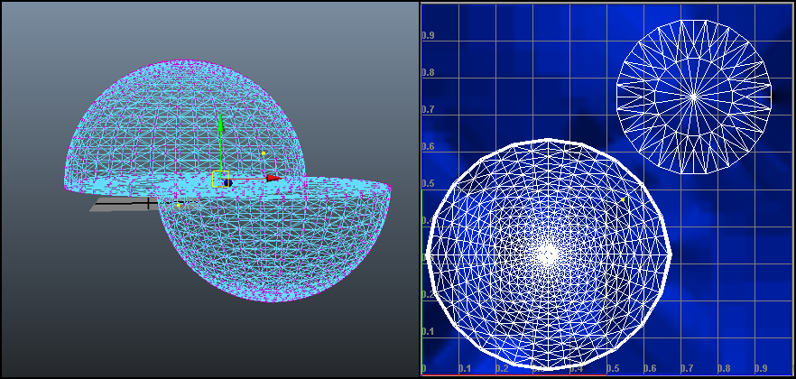
Scene aggregator on two identical half-sphere objects.
Scene Aggregator Example
One good example when to use the scene aggregator is when you want to combine objects to define a building, where each window is an instance of each other. The texture coordinates and materials for the windows are the same and the texture atlas will only store one material for all the windows in the building. In this way you get a resulting material/texture with much better resolution, compared to the one generated by the standard parameterizer, which will have to store materials for every window object.
In the figure above two half-sphere objects can be visualized, where one of them is an instance of the other. As their data (texture coordinates and material) is exactly the same, only one material need to be added to the final material/texture. One vertex in the UV texture editor refer to a vertex in both the top and bottom half-sphere objects.
Aggregator Settings
This settings object contains the settings relevant for the scene aggregator. Since the main function of the scene aggregator is chart aggregation, most of the relevant settings are located in the mapping image settings, which contains the controls for all parameterization.
Mapping image settings
This is the same settings object as in the reducer and remesher, please see the appropriate section for more information. Many of the settings that determine how the aggregation processor will behave are determined from the mapping image settings that start with SetChartAggregator[..] (e.g. SetChartAggregatorSeparateOverlappingCharts ).
Example
The following example shows how to run the aggregator.
void RunAggregationProcessor()
{
// Setup the scene here...
// Create the spAggregationProcessor
spAggregationProcessor aggregationProcessor;
aggregationProcessor = sg->CreateAggregationProcessor();
// Set the input scene
aggregationProcessor->SetScene(scene);
spAggregationSettings aggregatorSettings;
aggregatorSettings = aggregationProcessor->GetAggregationSettings();
// Set the BaseAtlasOnOriginalTexCoords to true so that the new texture
// coords will be based on the original. This way the four identical
// SimplygonMan mesh instances will still share texture coords, and
// when packing the texture charts into the new atlas, only rotations
// multiples of 90 degrees are allowed.
aggregatorSettings->SetBaseAtlasOnOriginalTexCoords(true);
// Get the mapping image settings, a mapping image is needed to
// cast the new textures.
spMappingImageSettings mappingImageSettings;
mappingImageSettings = aggregationProcessor->GetMappingImageSettings();
mappingImageSettings->SetGenerateMappingImage(true);
mappingImageSettings->SetGutterSpace(1);
mappingImageSettings->SetWidth(2048);
mappingImageSettings->SetHeight(2048);
mappingImageSettings->SetUseFullRetexturing(true); //replace old UVs
// If BaseAtlasOnOriginalTexCoords is enabled and
// if charts are overlapping in the original texture coords, they will be
// separated if SeparateOverlappingCharts is set to true.
mappingImageSettings->SetChartAggregatorSeparateOverlappingCharts(false);
// Run the process
aggregationProcessor->RunProcessing();
// Run the texture casting here...
}
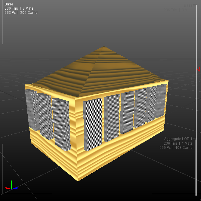
A scene including twenty objects and three materials
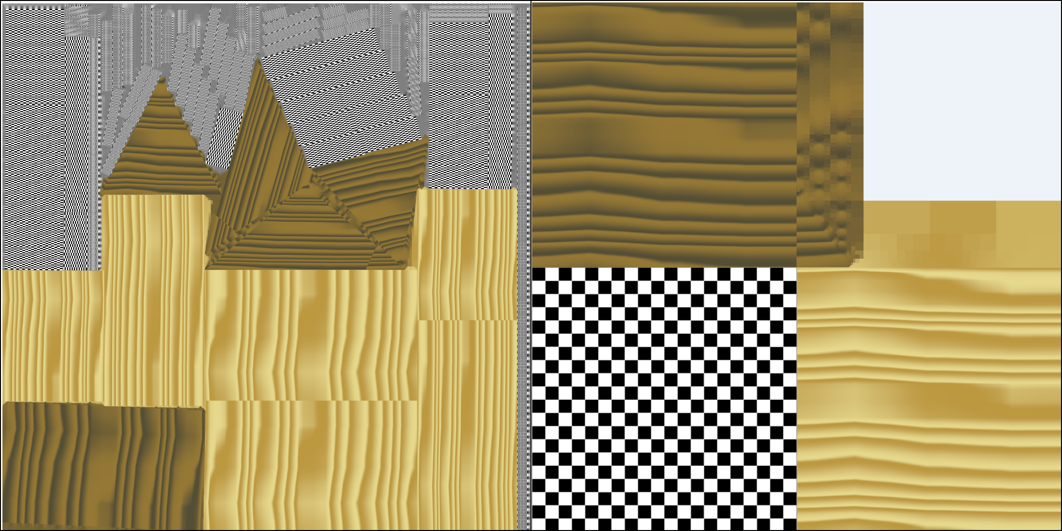
Difference in the final material when using scene aggregator (right) or the standard parameterizer in the reducer (left).
Occlusion mesh processor
The occlusion mesh processor is a relative to the remeshing processor, but it generates the new geometry solely based on the silhouette of the input geometry. This means internal features and concavities will be filled. The processor is designed in a way that will make the output mesh fall within the bounds of the silhouette of the original mesh at almost all times, making it useful for occlusion culling. Since it removes concavities it is not appropriate for shadow meshes that expect to self-shadow, but for pure casters it works very well. Due to the complexity of the task, this can be quite slow at higher settings.
Occlusion mesh Settings
This settings object contains the relevant settings for occlusion mesh generation, including options like silhouette fidelity and onscreen size.
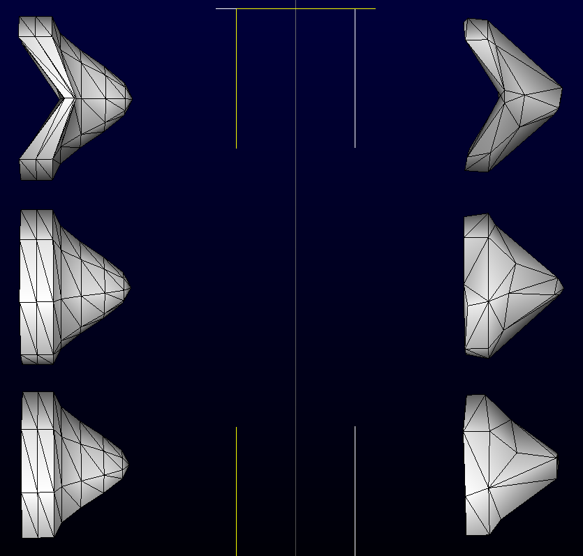
Occlusion meshes vs original meshes, seen from the front angles.
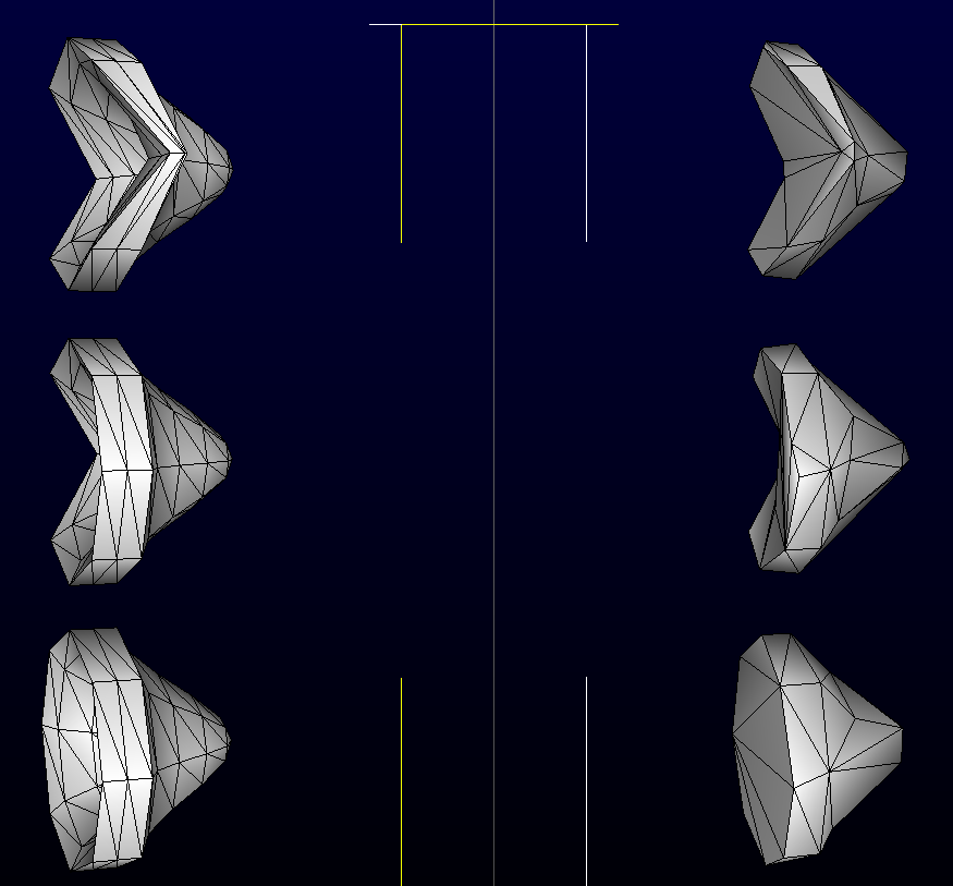
Occlusion meshes vs original meshes, seen from an angle. Note the filled concavities